Transformation of loads
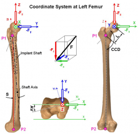
The loads (forces and moments) were measured in the implant-base coordinate system x’ y’ z’ (IBS). A force vector in the IBS is F’ = (Fx’, Fy’, Fz’), a moment vector is M’ = (Mx’, My’, Mz’). For the implant “HIP JOINT” the IBS was fixed to the left bone, for “HIP JOINT III”, “KNEE” and “SHOULDER” to the right bone. For subjects with implants at the opposite joint, the loads were first mirrored to the other side. Then they were transformed to the bone-based system x y z (BBS). A force vector in the BBS is F = (Fx, Fy, Fz), a moment vector is M = (Mx, My, Mz). Only for the knee joint and the spinal implants they were left in the implant-based system x’ y’ z’.
The example shows the coordinate systems IBS and BBS of an implant of type “HIP JOINT III”. Definitions of the coordinate systems of the other implants are described in the manual under the caption “Implants”.
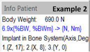
Relative to the BBS the implant is rotated three times in the order 1, 2, 3. The three rotation angles α1, α2, α3 are stated relative to the axes of the BBS! Their order and values are shown in the window “Info Patient” of the OrthoLoad videos:
In example 1 (implant type “HIP JOINT III”, right-sided implant) the three rotations and their order 1 2 3 are:
- clockwise by angle α1 = αx = +2° around axis +x
- clockwise by angle α2 = αy = -2° around axis +y
- clockwise by angle α3 = αz = -15° around axis +z
For this right-sided implant “HIP JOINT III”, a negative angle αz indicates an anteversion of the implant neck.
In example 2 (implant type “HIP JOINT III”, right-sided implant) the three rotations and their order 1 2 3 are:
- clockwise by angle α1 = αx = +17° around axis +z
- clockwise by angle α2 = αy = +8° around axis +x
- clockwise by angle α3 = αz = 0° around axis +y
For this left-sided implant an anteversion is indicated by a positive angle αz.
For transforming a force from the IBS x’ y’ z’ to the BBS x y z, three transformations have to be performed, using the transformation matrices T1 (α1), T2(α2), T3(α3). The complete transformation matrix T’ is then:
T‘ = T3 (α3) * T2(α2) * T1(α1) for F = T‘ * F’ (note the inverse order 3 2 1 of matrices!)
For transforming the loads from the BBS x y z to the IBS x’ y’ z’, this calculation has to be performed in the reverse order and with negative angles:
T = T1 (-α1) * T2(-α2) * T3(-α3) for F’ = T * F
Rotations around the axes x y z are performed by these matrices:

For example 1 the complete transformation matrices T’, T are therefore:
T‘ = Tz(-15°) * Ty (-2°) * Tx(2°) for F = T‘ *F’
T = Tx (-2°) * Ty(+2°) * Tz(+15°) for F’ = T *F

For example 2 they are:
T’ = Ty (0°) * Tx(8°) * Tz(17°) for F = T‘ * F‘
T = Tz (-17°) * Tx(-8°) * Ty(0°) for F‘ = T * F
Transformations of the moments M and M’ are performed separately in an analogue way.
Measuring Units % Body Weight and Newton
In the OrthoLoad videos, the loads are mostly reported in %BW (percent of body weight) for the forces and %BW*m for the moments, except for the spine implants were they are stated in Newton. The subject’s body weight in Newton is stated in the window “Info Patient” (examples see above). To transform loads from %BW/ %BW*m to N / Nm, the forces / moments have to be multiplied by 1% of the body weight, in example 1 by 7.809 and in example 2 by 6.9.


