Shoulder joint
Instrumented implant
The picture shows an instrumented shoulder implant capable of measuring forces, moments and, in addition, the temperature acting in the glenohumeral joint. It was developed in the Biomechanics Lab of the Charité and contains a measuring unit with 6 semiconductor strain gauges and a 9-channel telemetry transmitter. Each strain gauge requires one channel of the telemetry while the remaining three channels are used for transmitting the temperature, the current supply voltage and a synchronising signal. At the lower end, an inductive coil ensures the power supply. The measuring signals are led with a pacemaker feed-through to the antenna (protected by a cap of PEEK) which transmits the signals to the external measuring unit.
Coordinate system
Humerus system
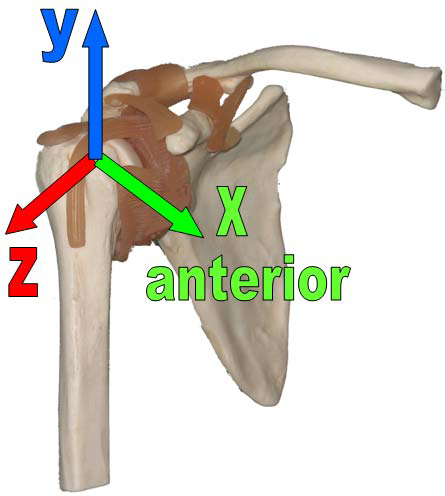
All loads are displayed as acting at the humerus. They are based on the ISB- recommended coordinate system (Wu et al., 2005) for the right shoulder joint. In this bone-based shoulder coordinate system, the positive x-Axis points in the anterior, the y-axis in the superior and the z-axis in the lateral direction. The moments Mx, My and Mz turn clockwise around the +x, +y and +z axes.
This system is right-handed for a right shoulder joint. For patient S3L, who obtained her implant on the left side, all values are mirrored to the right side to make it comparable to the other patients.
Implant system
In the implant-based coordinate system of the shoulder joint, the positive z-axis coincides with the neck of the implant and points in the medial- cranial direction. x- and y-axes are in the plane perpendicular to the implant neck. Axis x points laterally and y is oriented anteriorly. Load components relative to this implant-base system may be used to test fatigue or wear of implants, for example.
To obtain the forces and moments relative to the implant, the retroversion of the humeral head has to be known, indicated as α in the picture below. It can be measured relative to the anatomical landmarks of the epicondyles at the elbow or related to the orientation of the forearm in 90° elbow flexion as it is chosen during surgery (Hernigou et al., 2002). For some patients in OrthoLoad exact values for the retroversion to the epicondyles are available from a postoperative CT, taken for medical reasons. For the other patients a retroversion angle of 30° relative to the forearm in 90° elbow flexion was assumed as chosen by the surgeon during implantation.
The retroversion value for each patient can be found in the “Info Patient” window in OrthoLoad as the third rotation angle (picture below, right). In this example the given rotation angle of 63° corresponds to a retroversion angle of 27° (90°-63°). The other two angles are determined by the geometry of the implant and are therefore the same for all patients. The vector plot pictures (below, left) are simplified representations for better visualisation. The shown angle α is always the same and differs from the true angle in the patients.
General advice for the transformation of loads from a bone-based to an implant-based system is described here.
Scapula system
To obtain the loads relative to the scapula, a coordinate transformation would be required, taking into account the relative movement between humerus and scapula. This requires an accurate movement analysis. Such transformations are already planned but are not yet available.
Patients
 |  |  |  |
| S1R | S2R | S3L | S4R |
 |  |  |  |
| S5R | S6R | S7R | S8R |
Table with basic information about the shoulder joint patients:
| Patient | Side | Gender | Weight [kg] | Height [cm] | Age at Implantation [years] | Indication |
| S1R | right | m | 101 | 186 | 69 | Osteoartheritis |
| S2R | right | m | 85 | 161 | 61 | Osteoartheritis |
| S3L | left | f | 72 | 168 | 70 | Osteoartheritis |
| S4R | right | f | 50 | 154 | 80 | Osteoartheritis |
| S5R | right | f | 103 | 163 | 66 | Osteoartheritis |
| S6R | right | m | 135 | 186 | 50 | Osteoartheritis |
| S7R | right | m | 89 | 172 | 68 | Osteoartheritis |
| S8R | right | m | 83 | 173 | 72 | Osteoartheritis |
Hernigou, P., Duparc, F., Hernigou, A., 2002. Determining humeral retroversion with computed tomography. J
Bone Joint Surg Am 84-A, 1753-1762 (http://www.ncbi.nlm.nih.gov/pubmed/12377904). Wu, G., van der Helm, F.C., Veeger, H.E., Makhsous, M., Van Roy, P., Anglin, C., Nagels, J., Karduna, A.R., McQuade, K., Wang, X., Werner, F.W., Buchholz, B., 2005. ISB recommendation on definitions of joint coordinate systems of various joints for the reporting of human joint motion–Part II: shoulder, elbow, wrist and hand. J Biomech 38, 981-992 (http://www.ncbi.nlm.nih.gov/pubmed/15844264).


