Standard Loads Hip Joint
Downloads: PUBLICATION | DATA COLLECTION | VIDEO
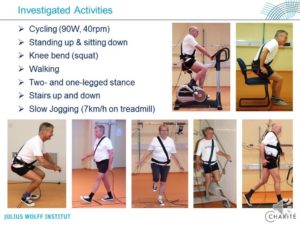
Many biomechanical studies on hip joints and their replacements require detailed knowledge of the loads acting in this joint. These loads widely depend on the performed activity, but additionally vary from one subject to the other. Because the whole possible load spectrum cannot be applied in such studies, a collection of typical loads was compiled. They are based on in vivo measurements in ten active subjects with instrumented hip implants during nine demanding and frequent activities of daily living. Two data sets define (I) average contact forces and frictional moments in subjects with an average body weight and (II) high forces and moments in subjects with a high body weight.
Because testing the fatigue endurance of hip implants is a major applications of such load data, the average and high forces were compared to those defined in the ISO standards for testing stem and neck. Evaluated were the spatial forces and moments as they act relative to the femur, but their transformation to an implant based coordinate system is described in the publication.
Additionally to the publication, an extensive data collection is accessible, containing the numerical data plus numerous diagrams which compare the loads during different activities and their individual deviations. The video gives animated explanations about the data, their evaluation and interpretation and proposes realistic test loads. It is well suited for educational purposes.
We hope that this data will help not only to improve future hip implants, but will also be applied in many other biomechanical studies regarding the hip joint!
PUBLICATION
Standardized Loads Acting in Hip Implants
G. Bergmann, A. Bender, J. Dymke, G. Duda, P. Damm
PLoS ONE 11(5): e0155612. doi:10.1371/journal.pone.0155612
Here are some examples from the published data:
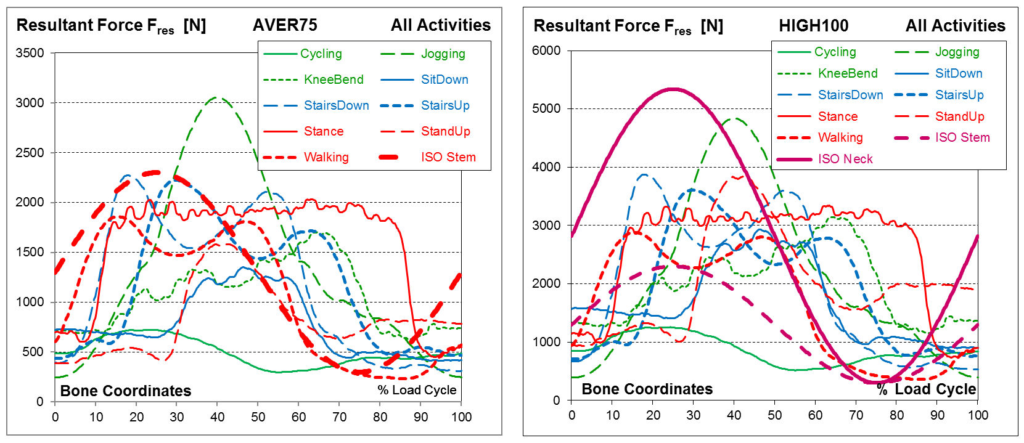
Left = average forces in subjects with average body. Right = high forces in subjects with high body weight. The resultant forces during nine activities of daily living are compared to the ISO forces, defined for endurance test on the neck of hip implants.
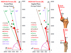
Small symbols = high in vivo peak forces in two planes during nine activities. Red line = force vector during walking (example). Open circle = ISO force for testing endurance of the implant stem. It is much smaller than all in vivo forces. The orientation of both ISO forces is unrealistic.
DATA COLLECTION
The data collection (196 MB) not only contains all numerical data from the average subject, used for the Plos One publication, but also more detailed data and diagrams from the individual subjects. The diagrams show, for example, the individual deviations of loads during the same activity. The time patterns of all forces and moments (Excel files) can be used for feeding analytical models and joint simulators.
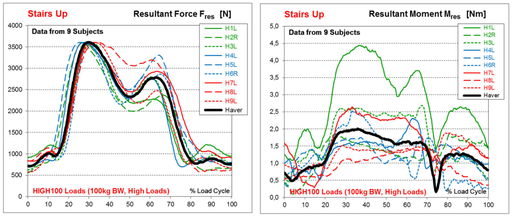
Left = resultant contact force. Right = resultant frictional moment. Data from 9 subjects when climbing one step of a staircase.
VIDEO
The video (143 MB, 1 hour) explains in detail how the in vivo measurements were taken and the average and high load scenarios were determined. The loads are compared to the two ISO test standards and proposals for more realistic 3D and uni-directional test forces are made.
Comparison to old data
The data base was now much enlarged, compared to the previous study (old data set), which was based on data from only four subjects:
Realistic loads for testing hip implants
Bergmann G, Graichen F, Rohlmann A, Bender A, Heinlein B, Duda GN, Heller MO, Morlock MM.
Bio-medical materials and engineering (2010) 65-75
The new loads somewhat differ from the old ones. It is recommended to use the new data.


