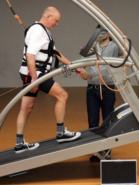
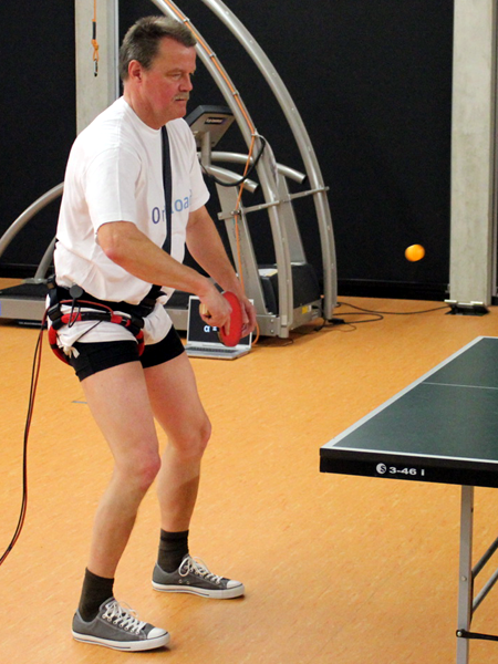
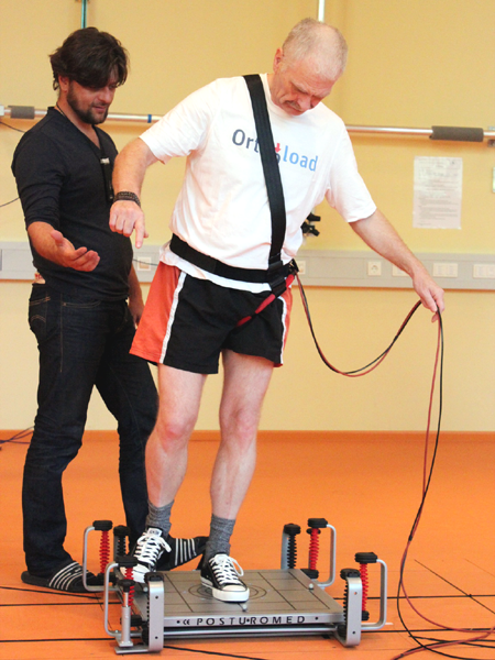
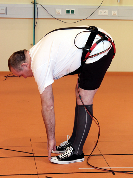
Forces, moments and temperatures are measured and transmitted by a multi-channel telemetry device. Results of the measurements with hip, knee, shoulder and spine implants are presented as video clips.
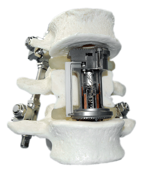
Severe compression fractures of a vertebral body or a tumour in the region of the spine sometimes require the replacement of a vertebral body by an implant. The loads on such an implant are not well known. In order to measure these loads, the commercially available vertebral body replacement ‘SYNEX’ was modified. It allows the in vivo measurement of three force components and three moments acting on the implant. The 9-channel telemetry transmitter developed in our biomechanics laboratory was placed into the cylinder of the implant together with 6 load sensors and a coil for the inductive power supply. Usually, the spine is in addition stabilized dorsally by an internal spinal fixation device implanted from the back side.
Implant: vertebral body replacement
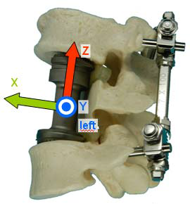
Coordinate system
The bone-based coordinate system was chosen according to ISO 2631. The x- axis in the median plane points anteriorly, the y-axis in the frontal plane to the left side, and the z-axis cranially.
The forces and moments are presented in the measuring units N and Nm.
Coordinate system Vertebral body replacement
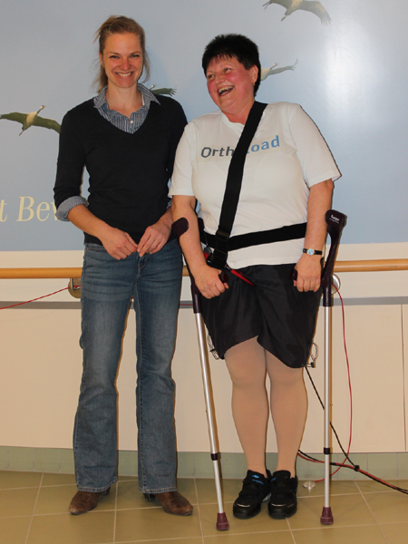
Patients
WP1
WP2
WP3
WP4
WP5
Table with basic information about those patients who had vertebral body replacements:
Little was known about the loads acting on internal spinal fixators. In order to measure the loads, a commercially available implant was modified. A measuring cartridge was integrated into the longitudinal rod containing six load sensors, an 8-channel telemetry transmitter, and the secondary coil for the inductive power supply.
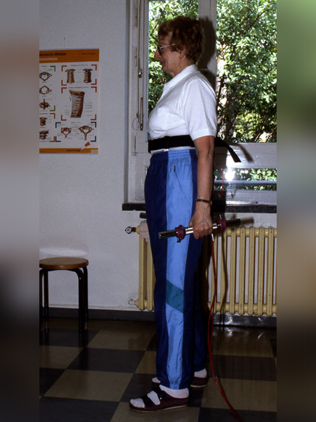
Both telemeterized fixators transmit their load values as a radio frequency pulse train outside the body. For the measurements, a flat power coil, fixed to the patient’s back, supplies the energy needed by both fixators. The power coil has an integrated antenna which delivers the signals to the external components of the telemetry system.
Implant: Internal spinal fixator
Coordinate system
The internal fixators were implanted pairwise. All reported data came from the left implant and are reported in a right-handed coordinate system.
The measured load components act at the centre of the cylindrical part of the implant. The z-axis is
the long axis of the fixator and points upwards. The y-axis is parallel to the axis of the Schanz screw and points ventrally. The x-axis is perpendicular to both others and is directed to the right side. All force components Fx, Fy, Fz act in axis directions while the moment components Mx, My, Mz turn clockwise around the axes.
Due to the anatomical conditions at the implantation site this coordinate system does not coincide exactly with the sagittal and frontal plane of the upper body. The forces and moments are presented in the measuring units N and Nm.
Patients
MS
NF
HS
FJ
JT
BB
JW
HB
LG
AG
Table with basic information about those patients who had instrumented spinal fixators:
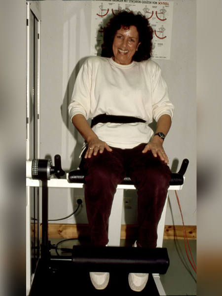
In order to obtain realistic loading data, a knee implant with a 9-channel telemetry transmitter was developed which enables six-component load measurements in a primary total knee replacement. Both forces in axial, medio-lateral and anterio- posterior direction and flexion-extension, varus-valgus and internal-external moments can be measured.The instrumented knee joint is a modification of the INNEXTM System, Type FIXUC (Zimmer GmbH, Winterthur, Switzerland). The standard femur component and tibial insert are used. Only the tibial component was modified to enable the integration of the electronic devices. During modification of the tibial component, the patients’ safety was deemed to be especially important.
Coordinate system
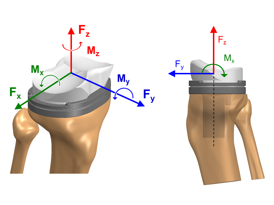
The coordinate system of the instrumented knee implant is a
a right- handed coordinate system fixed at the right tibial implant (not at the bone!). If forces and moments are measured in a left knee, they are transformed to the right side. The coordinate system is located at the height of the lowest part of the polyethylene insert. The z-axis is aligned with the stem axis of the implant.
The force components +Fx, +Fy and +Fz act in lateral, anterior and superior direction on the tibial tray. The moment Mx acts in the sagittal plane of the tibial component and turns clockwise around the +x-axis. The moment My acts in the frontal plane and turns clockwise around the +y-axis and the moment Mz turns clockwise
around +z-axis in the transverse plane. A positive moment Mz acts if the tibial implant component (or the femur) rotates inwards and/or if the tibia bone rotates outwards. The OrthoLoad videos show the load componentsrelative to the tibial tray. The stem axis z of the tibial implant component is rotated backwards in the sagittal plane by about 7 degree relative to the long axis of the tibia bone. This slope of the implant varies inter-individually.
Coordinate system knee joint
Patients
K1L
K2L
K3R
K4R
K5R
K6L
K7L
K8L
K9L
Table with basic information about the knee joint patients:
The picture shows an instrumented shoulder implant capable of measuring forces, moments and, in addition, the temperature acting in the glenohumeral joint. It was developed in the Biomechanics Lab of the Charité and contains a measuring unit with 6 semiconductor strain gauges and a 9-channel telemetry transmitter. Each strain gauge requires one channel of the telemetry while the remaining three channels are used for transmitting the temperature, the current supply voltage and a synchronising signal. At the lower end, an inductive coil ensures the power supply. The measuring signals are led with a pacemaker feed-through to the antenna (protected by a cap of PEEK) which transmits the signals to the external measuring unit.
Implant: Shoulder joint
Coordinate system
Humerus system
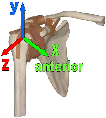
All loads are displayed as acting at the humerus. They are based on the ISB- recommended coordinate system (Wu et al., 2005) for the right shoulder joint. In this bone-based shoulder coordinate system, the positive x-Axis points in the anterior, the y-axis in the superior and the z-axis in the lateral direction. The moments Mx, My and Mz turn clockwise around the +x, +y and +z axes.
This system is right-handed for a right shoulder joint. For patient S3L, who obtained her implant on the left side, all values are mirrored to the right side to make it comparable to the other patients.
Coordinate System Shoulder Joint
Implant System Shoulder Joint
Implant system
In the implant-based coordinate system of the shoulder joint, the positive z-axis coincides with the neck of the implant and points in the medial- cranial direction. x- and y-axes are in the plane perpendicular to the implant neck. Axis x points laterally and y is oriented anteriorly. Load components relative to this implant-base system may be used to test fatigue or wear of implants, for example.
Implant System Shoulder Joint
To obtain the forces and moments relative to the implant, the retroversion of the humeral head has to be known, indicated as α in the picture below. It can be measured relative to the anatomical landmarks of the epicondyles at the elbow or related to the orientation of the forearm in 90° elbow flexion as it is chosen during surgery (Hernigou et al., 2002). For some patients in OrthoLoad exact values for the retroversion to the epicondyles are available from a postoperative CT, taken for medical reasons. For the other patients a retroversion angle of 30° relative to the forearm in 90° elbow flexion was assumed as chosen by the surgeon during implantation.
The retroversion value for each patient can be found in the “Info Patient” window in OrthoLoad as the third rotation angle (picture below, right). In this example the given rotation angle of 63° corresponds to a retroversion angle of 27° (90°-63°). The other two angles are determined by the geometry of the implant and are therefore the same for all patients. The vector plot pictures (below, left) are simplified representations for better visualisation. The shown angle α is always the same and differs from the true angle in the patients.
General advice for the transformation of loads from a bone-based to an implant-based system is described here.
Implant System Shoulder Joint
Scapula system
To obtain the loads relative to the scapula, a coordinate transformation would be required, taking into account the relative movement between humerus and scapula. This requires an accurate movement analysis. Such transformations are already planned but are not yet available.
Patients
S1R
S2R
S3L
S4R
S5R
S6R
S7R
S8R
Table with basic information about the shoulder joint patients:
Patient
Side
Gender
Weight [kg]
Height [cm]
Age at Implantation [years]
Indication
S1R
right
m
101
186
69
Osteoartheritis
S2R
right
m
85
161
61
Osteoartheritis
S3L
left
f
72
168
70
Osteoartheritis
S4R
right
f
50
154
80
Osteoartheritis
S5R
right
f
103
163
66
Osteoartheritis
S6R
right
m
135
186
50
Osteoartheritis
S7R
right
m
89
172
68
Osteoartheritis
S8R
right
m
83
173
72
Osteoartheritis
Literature:
Hernigou, P., Duparc, F., Hernigou, A., 2002. Determining humeral retroversion with computed tomography. J
Bone Joint Surg Am 84-A, 1753-1762 (http://www.ncbi.nlm.nih.gov/pubmed/12377904). Wu, G., van der Helm, F.C., Veeger, H.E., Makhsous, M., Van Roy, P., Anglin, C., Nagels, J., Karduna, A.R., McQuade, K., Wang, X., Werner, F.W., Buchholz, B., 2005. ISB recommendation on definitions of joint coordinate systems of various joints for the reporting of human joint motion–Part II: shoulder, elbow, wrist and hand. J Biomech 38, 981-992 (http://www.ncbi.nlm.nih.gov/pubmed/15844264).
The actual hip implant (Hip III) monitor the three force components and the three moment components acting on the ceramic head of the hip joint.
Instrumented implant
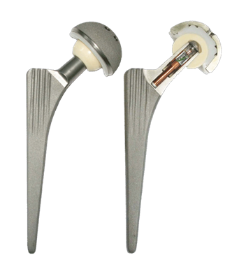
Hip III with one 9-channel transmitter
This new design of a instrumented hip implant was developed to measure contact forces and the friction at the joint in vivo. A clinical proven hip implant (‘Spotorno’ design) was modified in the neck area. The stem is build by TiAl6V4 and Al2O3- Ceramic was choosen for the implant head material. The neck was widened and enhanced with a 6.2 and 10mm hole. In the hollow neck are housed six semiconductor strain gauges, an internal induction coil and the telemetry. The six strain gauges are applied at the lower part on the inner wall (10mm hole) and connected to the 9-channel transmitter. The antenna, placed under the implant head, is connected by electronically feed-through to the internal telemetry. The feed-through is welded by a laser beam into the top plate. The hollowed neck is closed by the top plate and welded with an electron beam. Therefore the internal space is hermetically closed against the body fluids.
With this implant three contact forces acting onto the implant head center and three friction moments acting between the gliding partners can be measured in vivo.
Since April 2010 ten instrumented hip joints (Hip III) were implanted in ten patients (H1L, H2R, H3L, H4L, H5L, H6R, H7R, H8L, H9L and H10R) to monitor forces and moments. No further implantations are planned.
Implant Hip III
Coordinate system
Fermur system
All forces are reported in a right-handed coordinate system of the right femur (different from hip joint type I and II). The load components are reported as Fx, Fy, Fz. The femur system is fixed at the centre of the femoral head. The femoral midline (dotted black) intersects the axis of the neck in point P1. Point P2 is defined as the deepest point of the fossa intercondylaris at the distal end of the femur. The straight connection between P1 and P2 defines the z axis of the femur. The z axis of the coordinate system is parallel to the z axis of the femur.
The x axis of the coordinate system is defined perpendicular to z and parallel to a plane through the most dorsal parts of the condyles and points laterally. The y axis of the coordinate system is perpendicular to x and z and points ventrally.
Coordinate System ate right Femur
Implant system
In order to test fatigue or strength of the implant itself, it may sometimes be required to know the force components in an implant-based coordinate system. Axis zi of this system coincides with the shaft axis of the implant. The xi axis lies in the neck-shaft-plane. For the transformation of forces from the femur- to the implant system, three angles are required: angle Sx between the z axis of the bone and the shaft axis of the implant, angle Sy between the z axis of the bone and the shaft axis of the implant and furthermore the anteversion angle AV of the implant. These data are provided by the table in the video (“Info Patient”).
Turning the system by +Sx around the – x axis
Turning the system by +Sy around the – y axis
Turning the system by -Av around the + z axis
More details about this transformation are given here and in Bergmann et al. (2001) (http://www.ncbi.nlm.nih.gov/pubmed/11410170?dopt=Abstract).
Patients
H1L
H2R
H3L
H4L
H5L
H6R
H7R
H8L
H9L
H10R
Table with basic information about the patients with Hip III implants:
Patient
Side
Gender
Weight [kg]
Height [cm]
Age at Implantation [years]
Indication
H1L
left
m
73
178
55
Coxarthrosis
H2R
right
m
75
172
61
Coxarthrosis
H3L
left
m
92
168
59
Coxarthrosis
H4L
left
m
85
178
50
Coxarthrosis
H5L
left
f
87
168
62
Coxarthrosis
H6R
right
m
84
176
68
Coxarthrosis
H7R
right
m
95
179
52
Coxarthrosis
H8L
left
m
80
178
55
Coxarthrosis
H9L
left
m
118
181
54
Coxarthrosis
H10R
right
f
98
162
53
Coxarthrosis
For the hip joint III, the forces and moments in an implant-based coordinate system are of especial interest. The torque around the shaft axis, for example, is one of the most important parameters for the stability of implant fixation. To transform the forces measured relative to the bone, as delivered by OrthoLoad, to the loads acting in the implant system, the anteversion angle AV of the implant, the CCD angle and the neck length L are required. This data is listed in the following table:
Ground reaction forces were measured using two 6 degrees of freedom force plates (AMTI, Watertown, MA). The coordinate system is a right-handed system.
Raw data:
VARIABLE
DESCRIPTION
UNITS
SAMPLE RATE
Fx,y,z 1/2
Ground reaction forces, forceplate 1 and 2
N
960Hz
Mx,y,z 1/2
Moments relative to the original forceplate coordinate system, forceplate 1 and 2
Nmm
960Hz
For the calculation of the center of pressure the following offsets were used. The true origins of the coordinate systems are located below the top surfaces, with a distance (zo).
The resultant bending moment Mbend , acts in the middle of the femoral neck and perpendicular to the neck axis, and is calculated with the following formula:
with
The forces (Fx’, Fy’, Fz’) and moments (Mx’, My’, Mz’) are measured in the “implant coordinate system” x’, y’, z’ centered in the middle of the implant head. The force component Fx’ acts laterally, Fy’ anteriorly, and –Fz’ distally along the femur axis. The measured moment components Mx’, My’, and Mz’ turn right around the x’, y’, and z’ axes. N is the distance between the head center and the middle of the femoral neck and is equal to ½ L.
Mtne acts around the neck axis of the femur and represents the torsional loading of the neck. It is calculated by α = -45° rotation of the “bone coordinate system” around the y-axis.